|
|
Post by MartinT on Aug 14, 2015 18:40:42 GMT
Wish there were cases like that available back in my build days.
|
|
Deleted
Deleted Member
Posts: 0
|
Post by Deleted on Aug 14, 2015 19:50:59 GMT
Wish there were cases like that available back in my build days. God that would have save me lots of time and biscuit tins or even Roses Tin  I did eat the chocs first. |
|
Deleted
Deleted Member
Posts: 0
|
Post by Deleted on Aug 17, 2015 9:38:47 GMT
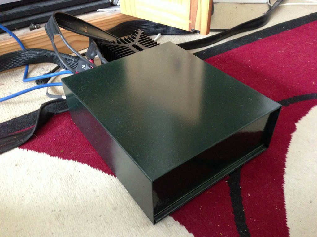
Here is David's Green Goddess I made him on veroboard a massive 5W/ch. A SECA design built from a scraped PC power supply. It is now about 4 years old and still playing UglyMusic . In a old test box with a plain pcb front panel all painted Green because I picked up the wrong colour paint can, whoops.  |
|
|
|
Post by MartinT on Aug 17, 2015 9:48:33 GMT
Recognising my UB cable there  |
|
Deleted
Deleted Member
Posts: 0
|
Post by Deleted on Aug 17, 2015 9:53:45 GMT
No it's a fake from China sorry.  |
|
|
|
Post by MartinT on Aug 17, 2015 19:19:38 GMT
|
|
|
|
Post by Sovereign on Aug 17, 2015 22:02:24 GMT
And my old man is Michael Jackson
|
|
Deleted
Deleted Member
Posts: 0
|
Post by Deleted on Aug 18, 2015 7:48:30 GMT
Fitted my new Selenium LDR volume control to my SECA kit, amazing performance, much better than the super pot I had, tracking left/right is 0.001% I think that should be fine.
James when I see you next you can have a listen.
|
|
|
|
Post by Sovereign on Aug 18, 2015 15:03:13 GMT
Sounds very interesting indeed!
|
|
Deleted
Deleted Member
Posts: 0
|
Post by Deleted on Aug 18, 2015 20:02:39 GMT
It was and sounds OK. Will build another when I can on a PCB not veroboard. The trick is no digital lies, totally linear.  |
|
|
|
Post by MartinT on Aug 18, 2015 20:19:25 GMT
Is that different from analogue lying?
|
|
Deleted
Deleted Member
Posts: 0
|
Post by Deleted on Aug 18, 2015 20:26:05 GMT
Oh yes, the thumps and crashes add ambient joy to music I think just like real life with kids crying and horns blowing. Not like "Deadenders" at all.
|
|
|
|
Post by Sovereign on Aug 18, 2015 20:27:47 GMT
Colin most of my days are free next week if you want to hook up
|
|
Deleted
Deleted Member
Posts: 0
|
Post by Deleted on Aug 18, 2015 20:47:01 GMT
Sorry James are full back and fore to hospital, and no music redheaded nurse yes but no music. A pooooo day all 4 of them.
|
|
|
|
Post by Sovereign on Aug 18, 2015 22:02:44 GMT
Totally free the following week as well at this stage, tipake your time, what ever suites you.
|
|
|
|
Post by MartinT on Aug 19, 2015 7:09:59 GMT
no music redheaded nurse yes but no music. Ah the nurses! The fun ones are generally not good looking and the beauties are often sour. I went for the fun ones every time! |
|
Deleted
Deleted Member
Posts: 0
|
Post by Deleted on Aug 20, 2015 19:15:29 GMT
More info on how to build. a SECA. Preparing components. Bend the resistor wire ends this is the 1K5 3W.  100mR or 0.1R 3W  The smaller resistors.  The resistors mounted.  Capacitor mounted. C5  The current control preset near the AD820 op-amp.  Fuse holder and 18-0, 0-18V power input for the transformer.  Bending and mounting the 6Amp diodes in the bridge rectifier.    Mounting the Green Led that is used to generate the ref voltage for the Current control. Note the long leg is near the hole it will be soldered into this is the Anode.   One of the two 33,000uF bulk capacitors note the stripe in the case it is the Negative terminal alway check these or big bang will be louder than the music   Mounting the Op-Amp AD820.  The BC337 transistor and the DC offset preset.  The drive transistors BD139 na BD140, see there orientation and the BD140 is on the right. Solder them closed as the PCB acts as a small heatsink. Also mount the BC337 close but not tight to the PCB. See above.  Here is the PCB,s I did for Ben, (thanks for the order Ben could do with more)  On set up insure the IQ preset is Anticlockwise and the DC offset is centre. PCB 1 , 5Hz - 100KHz Flat PCB 2, 5Hz - 100KHz Flat at full power (15W) in this case. DC offset -3.2mV 0.3mV I/P Z 13.5K 13.5K Damping 1150 1128 with a 250VA transformer tag on. Phase angle 20Hz - 20KHz -,+ 3.0 deg both PCB,s Boxed ready to go Ben Also not the insulators under the MOS FETs a small amount of heatsink compound only OK "U" yes you now who. |
|
|
|
Post by Sovereign on Aug 20, 2015 21:01:59 GMT
Thanks Colin
When I made my DAC it was the pictures on the DIY Audio thread that we more helpful than anything else
|
|
|
|
Post by Eduardo Wobblechops on Aug 21, 2015 7:28:42 GMT
Just me, but I would stand the higher wattage resistors off the board a little, for better cooling.
|
|
Deleted
Deleted Member
Posts: 0
|
Post by Deleted on Aug 21, 2015 8:21:42 GMT
Just me, but I would stand the higher wattage resistors off the board a little, for better cooling. No need under normal use as they are only dissipating a max of 750mW, just over kill by me. |
|