|
|
Post by petea on Jul 7, 2022 13:14:55 GMT
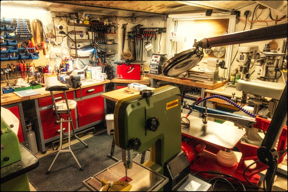
I have resumed my project to improve / update the workshop in the cellar here in Germany. I bought another lathe (Lorch LAS) and a larger milling machine (actually a Hommel UWG1, but it will mainly be used for milling and maybe surface grinding even though I have the lathe attachments) last year plus a Promiform Ultra saw etc. There was already some workbenches etc in the basement that I bought from the local DIY store when they were clearing out their display: I did try to to tell them that they must have the price wrong, but they were insistent that the whole lot was €60 and not just the wall cabinet! I used this mainly for benchwork, fixing things etc. I then added the Melcer lathe to give me more capacity than I had with the Frankenmat in the studio, but it was still rather limited compared with my workshop in the UK and I have a clock project and more automata in mind for here, hence the additional machines. What I next needed to do was the make some changes in the cellar (30 square metres) to separate storage from workshop and extend the benching to support the new mill etc. Original Benches and Cupboards from the DIY Clearance. . When we moved in about 20-odd years ago I bought a cheap woodworking bench to use to build kitchen cabinets etc for the apartment. It did the job, just, but was pretty crap as a woodwork workbench and the face and tail-vices were useless. I had strengthened the whole thing a few times, but decided that the best thing now was to remove the vices and convert it into a base for the milling machine etc. That is almost complete now. Hommel UWG1, Boley Sensitive Drill, Bandsaw and Fretsaw on the Modified Woodwork Bench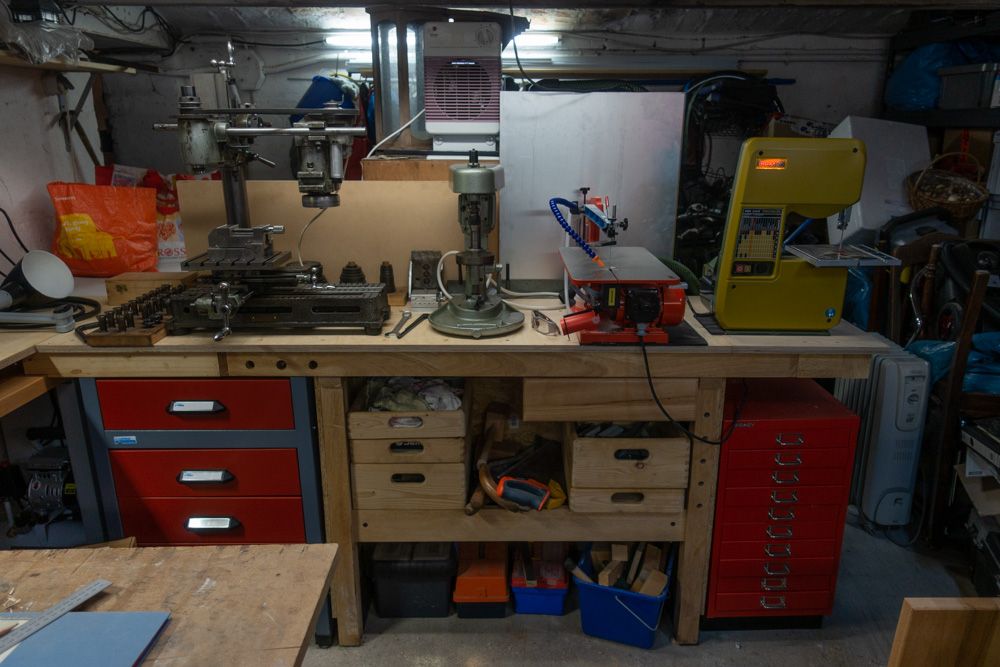 . I retained the tail-vice, but modified it so that it can be used to hold a removable section of bench-top. There are two removable pieces; one has a sliding cross-cut saw mounted to it; and the second (installed in the picture) has a small bandsaw and a disc sander mounted to it. I added a corner bench to maximise space and provide a better place for the small bench drill that used to live in the opposite corner. This abuts the stand for the Melcer lathe and the cross-cut saw lives under it when not in use. I also bought an additional drawer unit to match the 'bargain' one to house the attachments for the Hommel and a Bisley cabinet for machine tooling etc. Corner Bench Extension and New Cupboard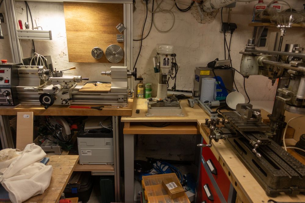 . The large space below the drill press will be fitted with a wooden shelf system for storing screws (in the compartment boxes), fittings etc and the small space will contain a surface plate. There is also a folding island bench that stands in the free space in the centre of the workshop (visible in the bottom-left of the above). The final side of the main space is occupied by the Lorch LAS. This will be run from a variable frequency drive / inverter so I can retain the 3-phase motor and original controls. It has a large selection of accessories, collets etc and I source spare, new cross-slide which will take an old Multifix tool-holder I had spare. Behind it you can see the bench below one of the windows on which is kept the grinding equipment. There is a lot of storage below that and shelving above. Lorch LAS with Grinding Bench Behind.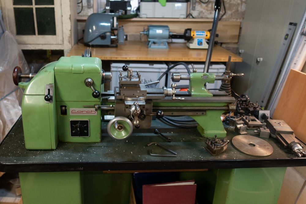 . In the remaining corner is the last of the bargain cabinets on which now stands the Profiform saw (the drill press used to be on it). Profiform Saw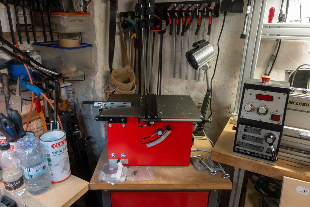 . There are a couple of bits of wiring to finish off and the under-shelf to install. The main task remaining though is to build a wall behind the old woodwork bench to separate the workshop area from the rest of the cellar. This will make it look much more organised and provide some vertical storage for collets etc and allow me to install the final wall-mounted machine lamp. There will be shelves on the other side of it as well. |
|
|
|
Post by speedysteve on Jul 7, 2022 13:43:05 GMT
That's a really nice space..
Great price on the cabs.
A joy to work in.
|
|
|
|
Post by petea on Jul 7, 2022 14:42:00 GMT
It is not as airy as the one in the UK (and a lot smaller), but I hope it will prove to be a good place to work in for longer periods than I have in the past. For one thing it is cool in the summer and does not get too cold in the winter and most of the time does not require any heating. Those cabinets and benching were an absolute steal. For very fine work I have the Frankenmat, a small Emco mill that I use as a drill and an Alessio precision mill in the studio. Speaking of which, I really need to move on to the next phase of the Frankenmat, Unimat conversion. I bought the Emco Unimat 3 lathe to do a couple of small model-making operations and it was fine for that. I do have a spare Cowells lathe I could have brought over from the UK, and I'm not sure now why I didn't. However, having got the Unimat I started acquiring accessories etc (as one does) and, before I knew it, I had three of the bloody things (one I have since given to a friend)! Having used it and also having Leinen machines to compare it with, several things began to niggle. At this point I should have just sold the lot and got a 'proper' lathe, but instead I decided that I would improve the Unimat. First up was to replace the horrid plastic control handles with proper ball-end ones and then to improve the action of the cross slide and main feed-screw (and tailstock). The problem was that the bearing surfaces on them are the cast allow from which they are made. So I machined that and added some good quality miniature thrust bearings and brass spacers. They now operate smoothly. I also added a DRO system and got rid of the original motor and added a 'proper' collet system that could accept 8 mm watch-makers collets. The motor mount was then changed so that it now sits in front of the lathe bed and has the speed and direction controls in a better location. Next up was a decent Multifix-style tool-holder. The whole lathe is mounted on a 'cabinet' stand made from bamboo into which more control features will be installed. Frankenmat Mk. 1 . Modified Cross-Slide Control . My next job is to change the primary belt to a toothed belt and pullies and swap the long belt for a Polycord one (I have it, but don't want to form it until I have done the belt conversion as it is pricey stuff). Then I will route the mains cable though the cabinet to an IEC connector and install a transformer and a high-torque, low speed DC motor in the rear of the cabinet. This will be coupled to the end of the lead-screw using a toothed belt and pullies to replace the dodgy, twisted rubber system that Emco uses to give powered feed. By keeping this belt relatively long I should be able to install a dog-clutch to enable one to switch the power feed in and out from the front of the cabinet and I will add a speed controller to that as well allowing one to choose the feed rate. I do have a set of after-market change gear for cutting metric threads (and the original Emco thread-chaser system which I won't use on this lathe), but it is not made that well. I am trying to decide whether to improve this (and maybe incorporate it into the power feed train) or to use a rotary encoder and servo drive to synchronise the spindle speed with the horizontal feed. Once the milling machine is up and running (or maybe when I'm back in the UK next) I might make a new cross-slide as that is a weak point on these lathes and limits their capability. Finally (for now!), I have some new headstock bearings to fit and at the same time I will either install a Hall Effect sensor in the headstock to measure spindle speed or, if I can find the right sort and size, install a rotary encoder on the main spindle. |
|
|
|
DIY
Jul 10, 2022 8:44:16 GMT
petea likes this
Post by brettj on Jul 10, 2022 8:44:16 GMT
I need to get on with my next task; building a firewood shed.
1.8 x 1.6 x 2.7m.
The weather for the next two weeks is shite, so will have to wait until it improves.
May be able to get the posts in as a beginning.
|
|
|
|
DIY
Jul 10, 2022 11:31:05 GMT
Post by petea on Jul 10, 2022 11:31:05 GMT
Do you have to build it out of firewood?!  |
|
|
|
DIY
Jul 18, 2022 14:45:02 GMT
Post by petea on Jul 18, 2022 14:45:02 GMT
I've been busy in the cellar again and have now installed the dividing wall and finished the benches. The last thing to do is to sort out the wiring a bit, install the phase inverters and the compressed air lines. I'll also add some shelving and mount collets etc on the new wall. I'm not sure I will keep the aluminium section in place though - it was just a bit left over from the kitchen facia boards. Bench with Dividing Wall Behind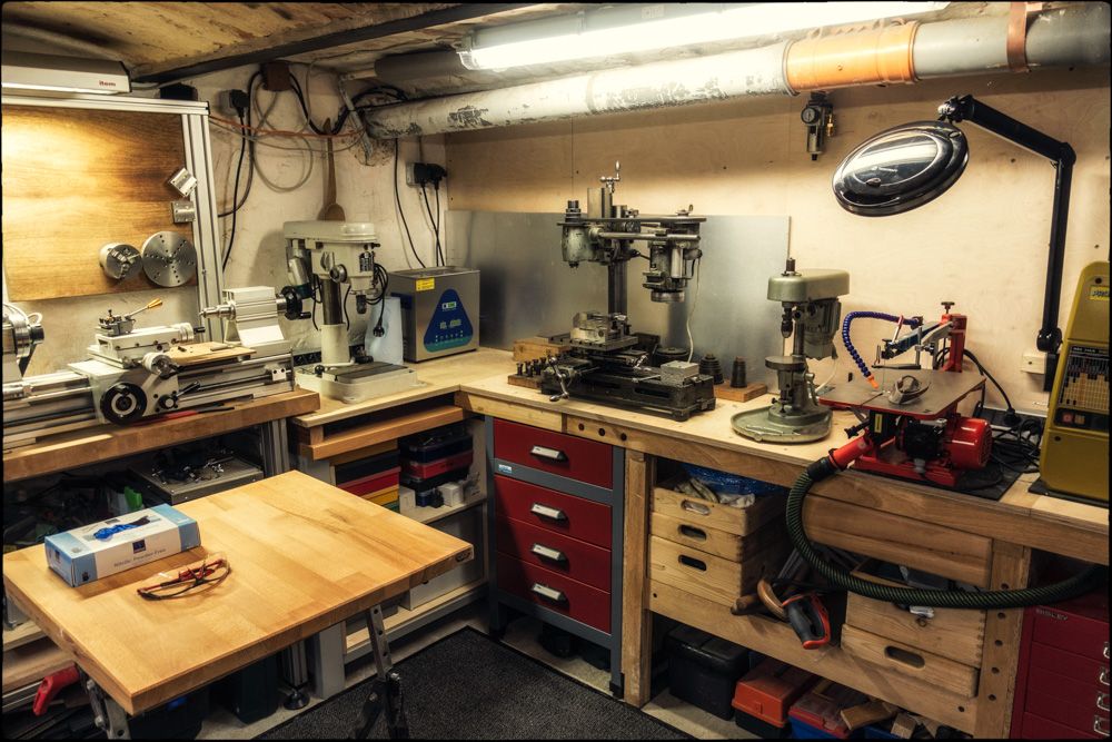 . Main Bench / Folding Island Bench
 . Hommel UWG1 & Boley BE2 Sensitive / High Precision Drill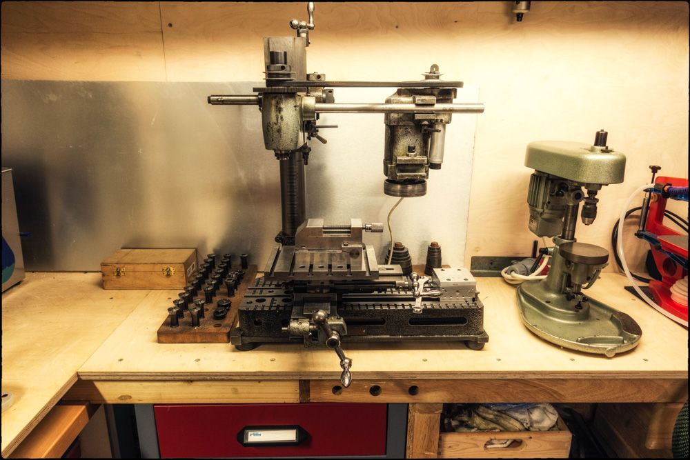 |
|
|
|
DIY
Jul 18, 2022 21:09:49 GMT
Post by stanleyb on Jul 18, 2022 21:09:49 GMT
I wished that I lived close to you! I got a hole to cut in an aluminium sheet but don't know anyone or of any company close by that can do it for me.
|
|
|
|
DIY
Jul 18, 2022 21:38:09 GMT
Post by petea on Jul 18, 2022 21:38:09 GMT
Where are you based? And what size / thickness of aluminium and what diameter does the hole need to be?
|
|
|
|
DIY
Jul 19, 2022 9:06:50 GMT
Post by stanleyb on Jul 19, 2022 9:06:50 GMT
I am in London. The hole is sort of a rectangle with rounded corners. Width is about 15cm and length 8cm.
|
|
|
|
DIY
Jul 19, 2022 9:27:27 GMT
Post by petea on Jul 19, 2022 9:27:27 GMT
I'm out near Basingstoke when in the UK, and have a workshop there also. The hole is 15 cm x 8 cm with rounded corners. How thick is the aluminium and how large is the overall sheet the hole needs to be cut in?
|
|
|
|
DIY
Jul 19, 2022 10:27:15 GMT
petea likes this
Post by stanleyb on Jul 19, 2022 10:27:15 GMT
I shall have to PM you further info after making some detailed measurements. I have the actual sheet with me. Maybe I should take a drive to Bsasingstoke as well...
|
|
|
|
Post by speedysteve on Jul 20, 2022 14:08:44 GMT
The hoop bending project nears it's end. Wooden frame made from pressure treated timber. The corner triangles are double thickness and drilled to receive the hoop posts. Expanding Urethane foam glue is great! The centre bar is glued / stout wire wrapped on.  Apparently you can never have enough polytunnels! So the gardener tells me 🙂 These mini ones are just right for the garden size and manageable. Hinged so they can be opened. I've got to make the prop legs, so it can be ajar, and I fit a rope to allow wider / full opening. Also a means of lashing them shut during the winter or summer storms. We'll wait with the sheeting until what's growing there now has gone over. That is stapled on and then a further strip of pressure treated timber screwed on. |
|
|
|
Post by speedysteve on Jul 30, 2022 13:50:21 GMT
Back on the powdercoat dislike, and what to do about it. We have 5 quality outdoor lanterns at the front of the house. 5 at the rear, and two cheaper ones at the side. We priced them 7 years ago when we bought the house. £65 each - ouch! Not B&Q cheapies. They are cast aluminium, black powdercoated. Look nice when new (doesn't everything?🙂). Aluminium corrodes to white aluminium oxide and this forms a protective layer that pretty much won't corrode further, as long as the oxide layer is undisturbed. Once the corrosion gets under the powdercoat, be it from a chip of imperfection or not adhering properly or edge, it quickly spreads causing the plastic like thin powdercoat layer to flake. Here are some stills to illustrate     Last year I removed 2 of the lanterns and wirebrushed and sand blasted them to remove as much of the powdercoat as possible. The problem is that where it's still adhering, it's a devil of a job to remove. Some of the nooks and crannies were impossible. I spray painted an aluminium etch primer base coat and satin black finishing coats. Took ages, used up lots of paint.. Looked like new! I refitted and after a year sitting in the elements, there are some signs of corrosion again. Give them 6 or 7 years.. This year, the remaining bunch look pretty sorry for themselves. There had to be a better faster way.. |
|
|
|
DIY
Jul 30, 2022 13:56:28 GMT
Post by MartinT on Jul 30, 2022 13:56:28 GMT
Hammerite or something equally robust?
|
|
|
|
Post by karatestu on Jul 30, 2022 13:56:45 GMT
Back on the powdercoat dislike, and what to do about it. We have 5 quality outdoor lanterns at the front of the house. 5 at the rear, and two cheaper ones at the side. We priced them 7 years ago when we bought the house. £65 each - ouch! Not B&Q cheapies. They are cast aluminium, black powdercoated. Look nice when new (doesn't everything?🙂). Aluminium corrodes to white aluminium oxide and this forms a protective layer that pretty much won't corrode further, as long as the oxide layer is undisturbed. Once the corrosion gets under the powdercoat, be it from a chip of imperfection or not adhering properly or edge, it quickly spreads causing the plastic like thin powdercoat layer to flake. Here are some stills to illustrate     Last year I removed 2 of the lanterns and wirebrushed and sand blasted them to remove as much of the powdercoat as possible. The problem is that where it's still adhering, it's a devil of a job to remove. Some of the nooks and crannies were impossible. I spray painted an aluminium etch primer base coat and satin black finishing coats. Took ages, used up lots of paint.. Looked like new! I refitted and after a year sitting in the elements, there are some signs of corrosion again. Give them 6 or 7 years.. This year, the remaining bunch look pretty sorry for themselves. There had to be a better faster way.. Plastidip ? |
|
|
|
DIY
Jul 30, 2022 14:21:40 GMT
Post by petea on Jul 30, 2022 14:21:40 GMT
I would have taken the same approach, Steve: etch primer and then a topcoat. What did you use for the final coat? Maybe an automotive lacquer after?
|
|
|
|
Post by petea on Jul 30, 2022 15:24:11 GMT
I mentioned elsewhere, and Martin has commented similarly, that the EtherREGEN and its PSU from Uptone Audio run very, very hot. Martin has placed a heatsink on his and I intended to do the same and now that the parts have arrived, today I put them together. I decided to use 2 heatsinks attached to a 3 mm-thick brass plate on each. I am a bit restricted for height and that limited my choice of heatsink: I would have preferred ones with deeper fins, but I'll see how these perform. www.amazon.co.uk/gp/product/B08R93BCMT/ref=ppx_yo_dt_b_asin_title_o00_s02?ie=UTF8&psc=1Here are the materials laid out (and partly marked-up). The plan was to fit the heatsinks to the brass plate with screws and thermal adhesive. The plate is 3 mm thick and machined to 60 mm x 100 mm with a slight bevel on the edges of the faces that contact the EtherREGEN and its PSU. 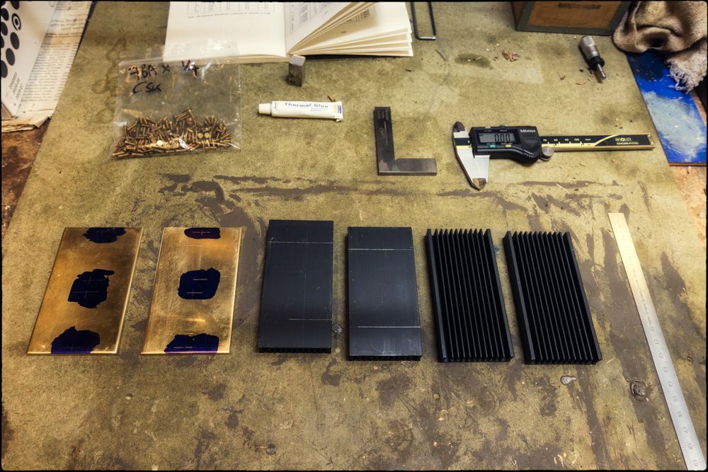 The next step was to finish marking out the positions of the holes for the screws that attach the heatsinks to the brass plates. I planned to use 7 BA counter-sunk screws inserted from the underside into holes tapped in the heatsinks.  After marking the centres of the holes the heatsinks were positioned on the brass plates and held with tape. 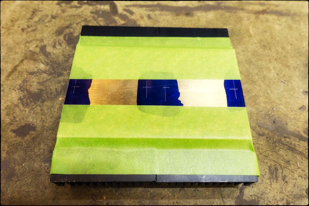 The centres were then punched using an optical punch (the old eyesight is not what it used to be!). View Through the Centre Finder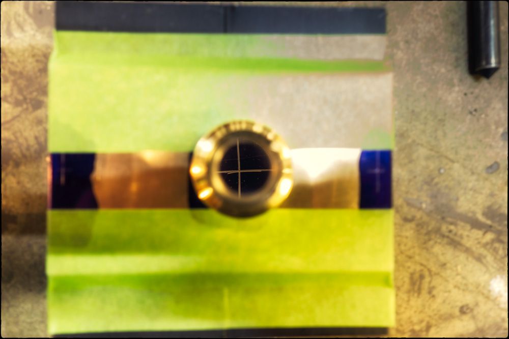 Centres Punched Centres Punched The holes were then spot-drilled and then through-drilled to the tapping diameter for a 7 BA thread using a high-speed, drill. 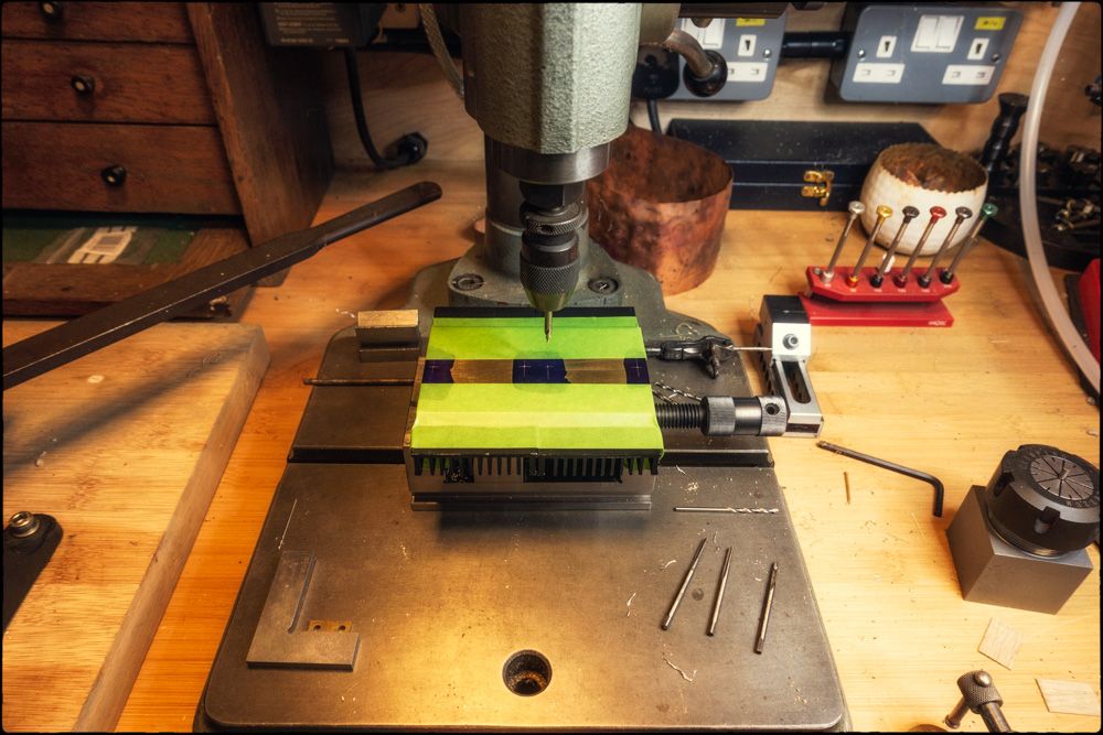 The heatsinks were then removed from the brass plates...  the plate was then mounted over parallels on a larger vice....  and the holes in the brass were enlarged to the clearance diameter for a 7 BA screw.  The plan was to use counter-sunk screws and these needed to be just below the bottom surface of the plate. A counter-sink of 1.5 mm looked to be ideal, but I decided to make sure that the angle of the sides of the screw heads was 90º as that was the angle of the counter-sink I planned to use. A screw was mounted in a small scrap of aluminium and then checked on the measurement microscope. As can be seen from the second image, it was indeed 90º. 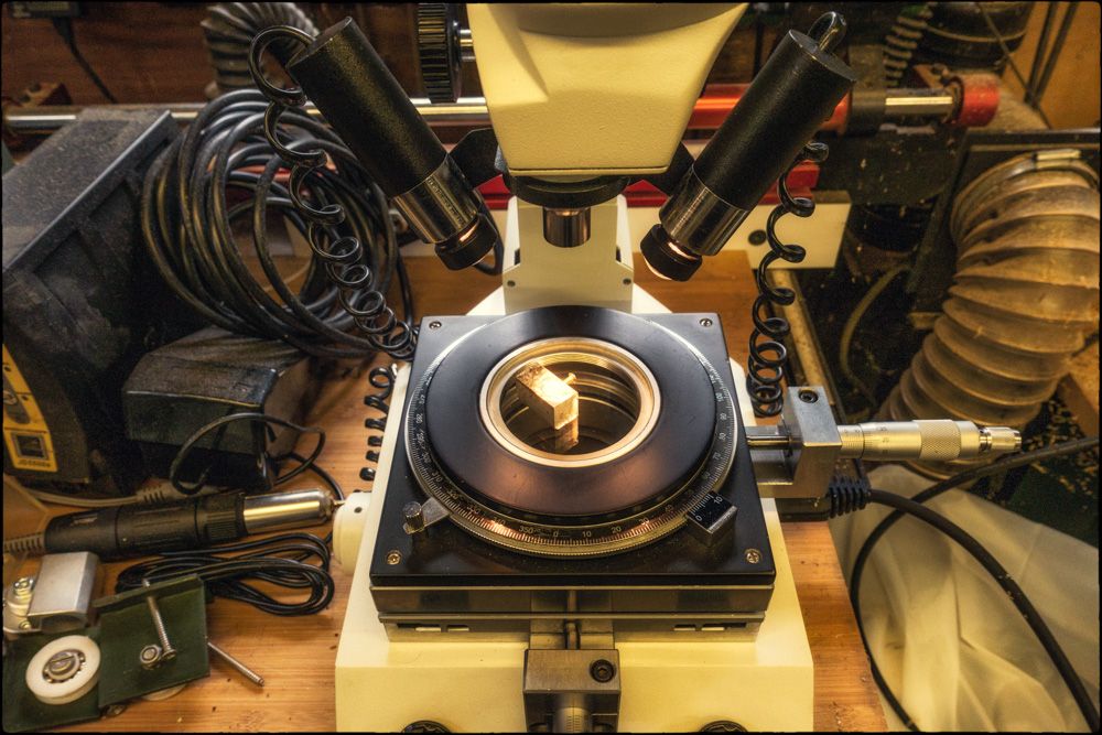 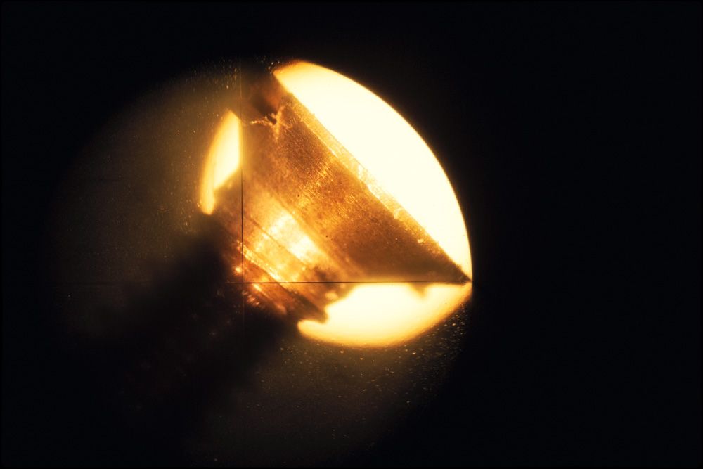 Unfortunately, the chuck on the high precision drill is too small to accept the counter-sink I planned to use and the large drill press is not ideal for repeat drilling holes to a depth of only 1.5 mm! So I had to resort to using one of the milling machines instead. A plate was mounted in a milling vice and then the countersink was mounted in a 5 mm-diameter collet, centred on a hole and the Z-axis of the mill was set to zero on its digital scale. The counter-sinks were then milled to a depth of 1.5 mm. A Brass Plate Mounted on the Mill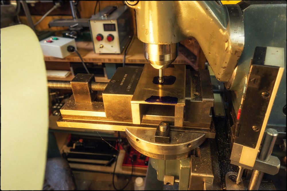 Setting the Z-Axis Setting the Z-Axis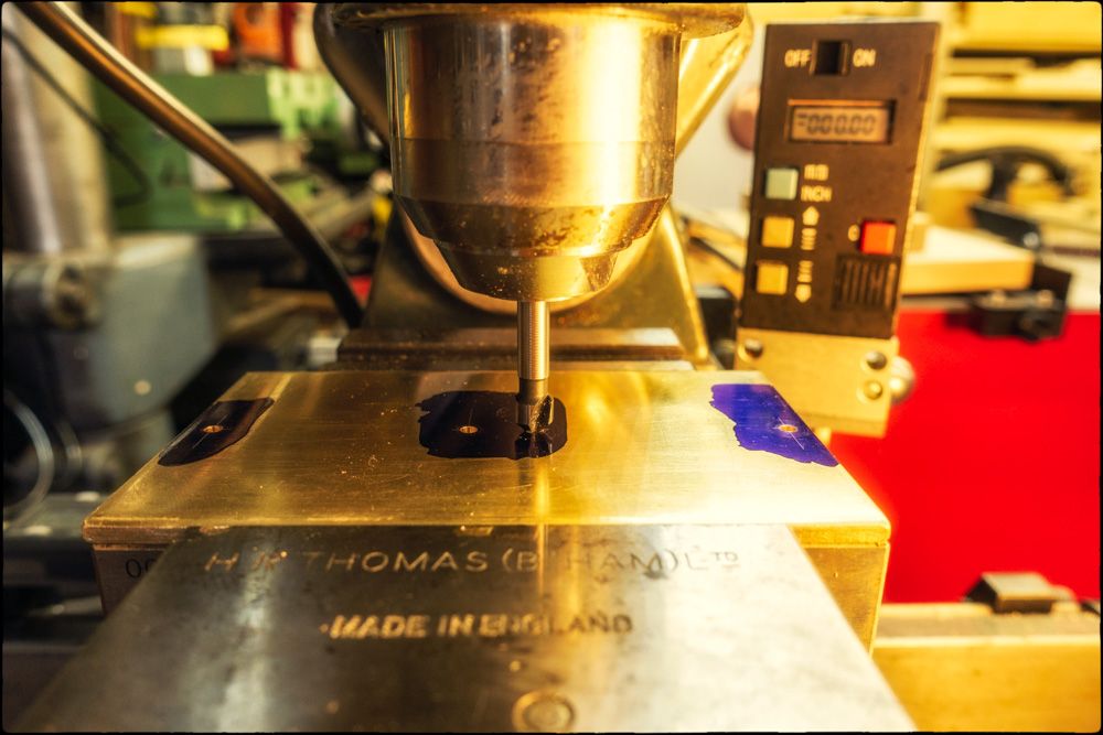 Milled Counter-Sinks Milled Counter-Sinks  The next stage was to thread the holes in the heatsinks to 7 BA. This was done manually using a 7 BA second-tap held in the high precision drill. They were then de-burred along with eight screws. 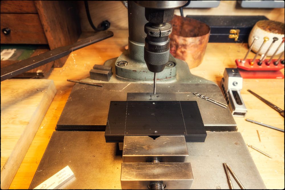  The rear of the holes in the brass were then de-burred and then the faces destined to be in contact with the Uptone units were given a matt finish using 50 µm glass beads and then cleaned and de-greased. 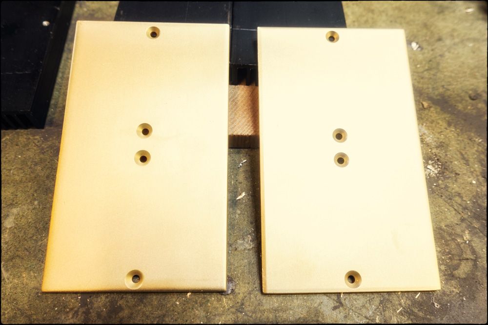 The heatsinks were then attached using both thermal adhesive and 4 x 7 BA brass screws.  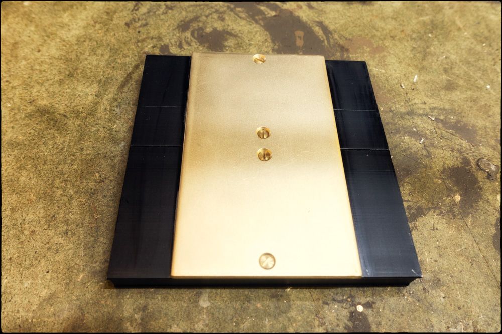 Here is one of the finished heatsinks (still needed a clean at this stage). 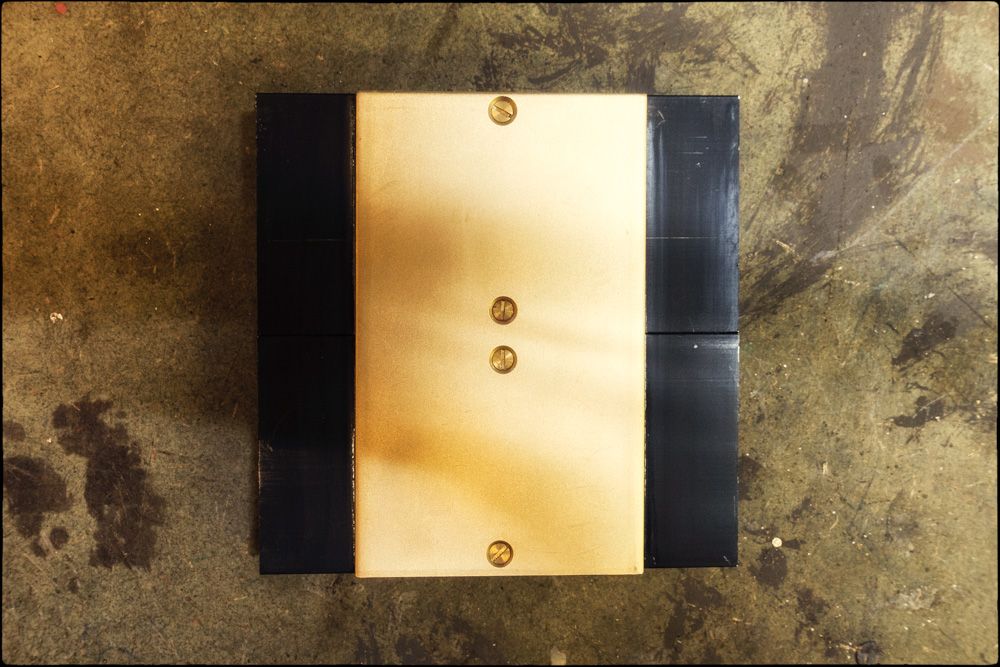  And here is one sitting on top of the PSU. They weigh 310 g each and sit firmly on the units. However, I will eventually hold them in place, maybe just with cable ties though. I'll check how they perform first. 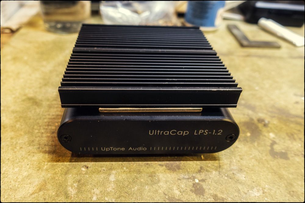 |
|
|
|
DIY
Jul 30, 2022 16:45:40 GMT
Post by MartinT on Jul 30, 2022 16:45:40 GMT
Nice work. 7BA? Slotted bolts? Have you gone all imperial of late?  |
|
|
|
DIY
Jul 30, 2022 17:10:18 GMT
Post by petea on Jul 30, 2022 17:10:18 GMT
BA is, perversely, a metric thread form! I actually used a 2.5 mm x 0.45 mm pitch tap as I couldn't find my BA 7 one: I have since given up looking and ordered some NOS ones from eBay!
|
|
|
|
Post by speedysteve on Jul 30, 2022 20:14:35 GMT
Looks great.
Did they get hot then?
Plastdip = as hard work as paint and not sure that would stick well to bare / aluminium oxide.
One nick and the whole lot would be off in a few years, or perhaps swell up like a rubbery plasticy balloon around the corroding aluminium oxide powder, that was once the lantern🙂
I went for something that did not need removal of the lanterns, a quick wirebrushing / scrape of all lose powdercoat and super quick to brush on hit...!?
Did all the remaining lanterns in an hour or so.
|
|


