Post by Deleted on Jul 23, 2019 19:25:36 GMT
Well having spent a lot of time this year on various projects this year, one of them being clocks (crystal oscillators, accurate timing devices for signal integrity).
Clocks have many functions in electronics, not just audio.
However for this thread audio relevance is key shall we say. Lots of so called high performance clocks are now available claiming ultra low jitter figures (Jitter simply put the (timing) difference (errors) between the audio data (PCM) and the alignment signal (clock signal).
The less jitter, the less deviations from the desired timing cycle should result in a more desirable sound being produce providing all things are equality the reconstruction stage of the dac (I/V stage) YMMV
Wiki's brief round up
Jitter may be caused by electromagnetic interference and crosstalk with carriers of other signals. Jitter can cause a display monitor to flicker, affect the performance of processors in personal computers, introduce clicks or other undesired effects in audio signals, and cause loss of transmitted data between network devices. The amount of tolerable jitter depends on the affected application.
This is a small post to illustrate how some times theory doesn't always imitate real world results.
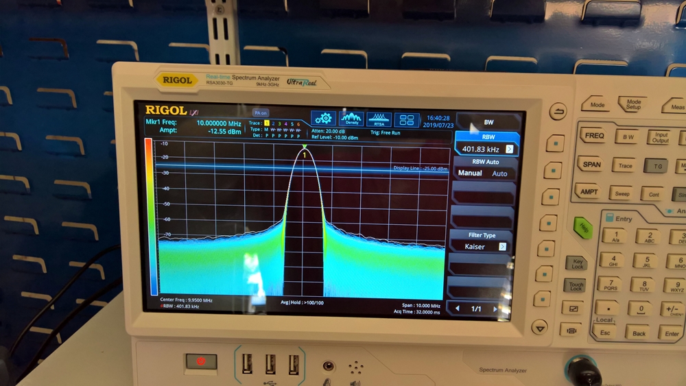
Below is a screen shot of a very high regarded clock manufacturers 10 Mhz clock with a dedicated ultra quiet power supply feeding it.
First image is of the wave form being viewed in real time, analyser bandwidth span is set to 10Mhz from 5 to 15Mhz with the RBW is set to just over 400Khz, as you can see it is a very decent result with virtually no side-bands presents, very low noise floor as pre amplifier is switch on. Looks damn fine.

All going very well.
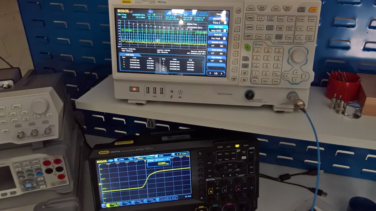
Below is the same clock viewed on a high definition scope and the analyser set to FFT mode (spectrum analysis fast Fourier transfer) or a great way at looking at how the device under test (the clock) behaves at much higher frequencies.
Now you can see the harmonic distortion happening right up the bandwidth I set for the test up to 500Mhz,as you can see the harmonics are pretty even, and range from -21dbm down to -37dbm at the much higher frequencies. Although the numbers are not really bad it shows that the 'rf noise' extends to over 50 times the cited original frequency (and beyond I did measure up to 800Mhz and the harmonic artifacts were still visible just a lower noise measurement)
So what does it really mean for most of you, pretty much bugger all
However it can and does affect your digital replay system depending on how well the clock circuit has been implemented, whether attention has been paid to RF control / harvesting, power supply cleanness, circuit board layout etc.
The upshot is as Martin T can elaborate, all that glitters is not gold with some of the highly rated clocks, even a modest clock well implemented can sound more natural than some of the uber low ps rated clocks.
Just thought it may interest a few of you.

Clocks have many functions in electronics, not just audio.
However for this thread audio relevance is key shall we say. Lots of so called high performance clocks are now available claiming ultra low jitter figures (Jitter simply put the (timing) difference (errors) between the audio data (PCM) and the alignment signal (clock signal).
The less jitter, the less deviations from the desired timing cycle should result in a more desirable sound being produce providing all things are equality the reconstruction stage of the dac (I/V stage) YMMV
Wiki's brief round up
Jitter may be caused by electromagnetic interference and crosstalk with carriers of other signals. Jitter can cause a display monitor to flicker, affect the performance of processors in personal computers, introduce clicks or other undesired effects in audio signals, and cause loss of transmitted data between network devices. The amount of tolerable jitter depends on the affected application.
This is a small post to illustrate how some times theory doesn't always imitate real world results.
Below is a screen shot of a very high regarded clock manufacturers 10 Mhz clock with a dedicated ultra quiet power supply feeding it.
First image is of the wave form being viewed in real time, analyser bandwidth span is set to 10Mhz from 5 to 15Mhz with the RBW is set to just over 400Khz, as you can see it is a very decent result with virtually no side-bands presents, very low noise floor as pre amplifier is switch on. Looks damn fine.

All going very well.
Below is the same clock viewed on a high definition scope and the analyser set to FFT mode (spectrum analysis fast Fourier transfer) or a great way at looking at how the device under test (the clock) behaves at much higher frequencies.
Now you can see the harmonic distortion happening right up the bandwidth I set for the test up to 500Mhz,as you can see the harmonics are pretty even, and range from -21dbm down to -37dbm at the much higher frequencies. Although the numbers are not really bad it shows that the 'rf noise' extends to over 50 times the cited original frequency (and beyond I did measure up to 800Mhz and the harmonic artifacts were still visible just a lower noise measurement)
So what does it really mean for most of you, pretty much bugger all

However it can and does affect your digital replay system depending on how well the clock circuit has been implemented, whether attention has been paid to RF control / harvesting, power supply cleanness, circuit board layout etc.
The upshot is as Martin T can elaborate, all that glitters is not gold with some of the highly rated clocks, even a modest clock well implemented can sound more natural than some of the uber low ps rated clocks.
Just thought it may interest a few of you.


 📶NAS > Gustard x26p DAC > Benchmark LA4 Pre-Amp > NAD M22-V2 Amplifier > Revel F228Be Speakers

