Deleted
Deleted Member
Posts: 0
|
Post by Deleted on May 11, 2015 11:47:13 GMT
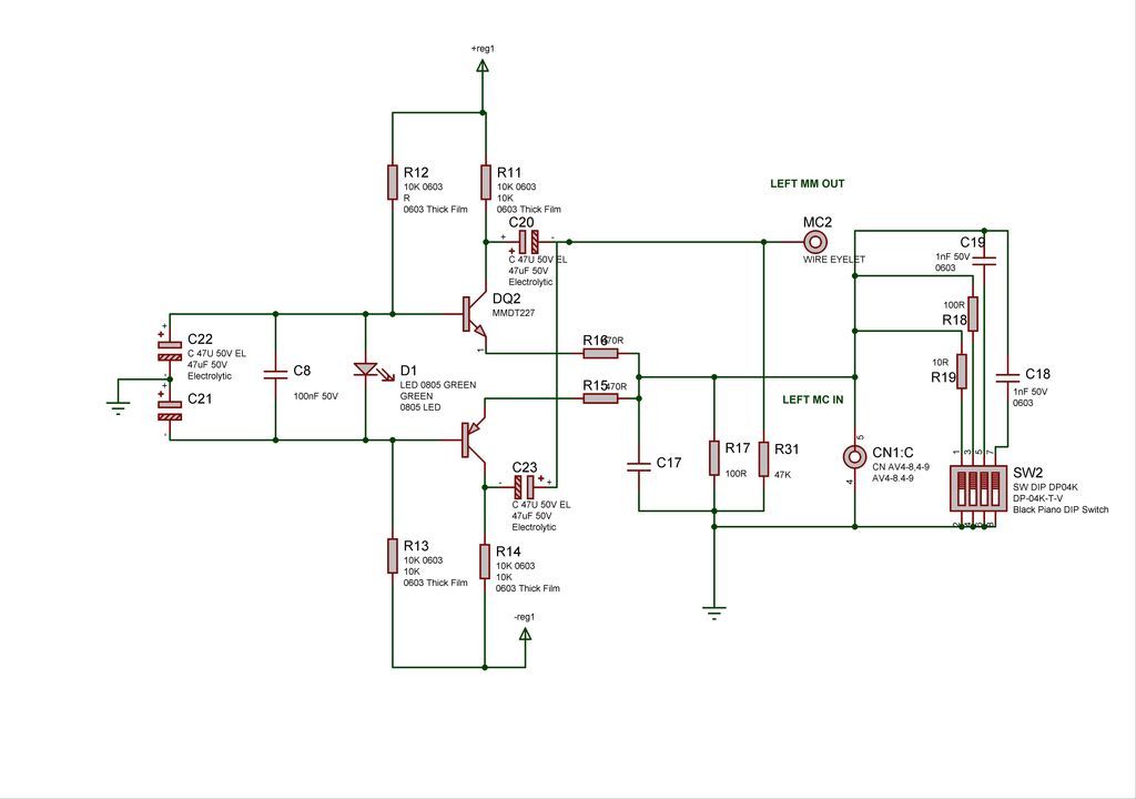
Here is a nice MC - MM head circuit a version of which I used in the Magnum Amps, but now with much better components.  |
|
|
|
Post by MartinT on May 11, 2015 13:40:09 GMT
Sorry Overvolt should read over current me thinks. Yes, I saw that it has voltage sensing for over-current protection and then wrote the wrong thing <slap>!
Nice little circuit, that, and scalable to a degree.
|
|
Deleted
Deleted Member
Posts: 0
|
Post by Deleted on May 11, 2015 16:00:34 GMT
I suspected a typo, no slap this time  Yes I have that cct driving FET's and it performed lovely. The PNP and NPN are a quad pack so the left and right channel had the same ref volts (green led) why green led? mm well they produce 10dB less noise so well worth using, it is prone to PSU noise so that has to be excellent but simple design. The nice thing is the input is at 0V. BW up to a few hundred megahertz. So worked well on the old FM radio well. |
|
|
|
Post by Chris on May 11, 2015 22:46:48 GMT
Long-tailed pair with a current sink, standard driver configuration with quiescent current adjuster, common collector push-pull output pair with over-volt drive protection, standard overall NFB with compensation, Zobel network on the output? Presumably class AB. I was going to post exactly that earlier but I got busy.  |
|
|
|
Post by MartinT on May 11, 2015 22:47:32 GMT
|
|
|
|
Post by ChrisB on May 12, 2015 5:59:49 GMT
He-heh!
|
|
|
|
Post by Chris on May 16, 2015 9:09:47 GMT
So built this kit up,plugged it into a 12v adaptor and nothing. Thought I might have at least got a power light but nothing at all.
Any ideas? My thoughts are poor quality soldering not making a good connection?
|
|
|
|
Post by Eduardo Wobblechops on May 16, 2015 9:34:33 GMT
Polarity correct?
|
|
|
|
Post by Chris on May 16, 2015 14:43:25 GMT
How would I check that mate?
Seems I've put things in the only way they can go.
|
|
|
|
Post by Eduardo Wobblechops on May 16, 2015 14:59:45 GMT
How are you connecting the power supply to the board?
|
|
|
|
Post by Chris on May 16, 2015 15:36:17 GMT
There's an input for it - just a round socket like you find on laptops and the like. Just plugging the 12v adaptor into that.
|
|
|
|
Post by Eduardo Wobblechops on May 16, 2015 17:09:02 GMT
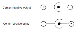
Ok, just wondered if the polarity was wrong. Normally the centre pin or inside of the barrel is positive on the plug - it will say on the power supply.
Do you have a multimeter?
|
|
|
|
Post by Chris on May 16, 2015 17:31:18 GMT
No mate,just a broken one. Not much use really.
|
|
|
|
Post by Eduardo Wobblechops on May 16, 2015 17:49:38 GMT
Well it would do for chucking at your tosser of a manger...
|
|
|
|
Post by Eduardo Wobblechops on May 16, 2015 17:54:25 GMT
If you look at the picture on eBay of the amp, see the drawing next to where you would plug the power supply in to?
Shows that it wants the inside to be positive, and the outside negative. Does the same picture appear on your power supply, and say the same thing?
|
|
|
|
Post by Chris on May 16, 2015 19:16:30 GMT
  Here's what I've ended up with and the power supply. Think you might be right... |
|
|
|
Post by Eduardo Wobblechops on May 17, 2015 6:58:16 GMT
See the picture on the white label, the one that looks like three circles in a row?
Take a close up pic of that.
BTW, did this come as a kit of parts which you soldered?
|
|
|
|
Post by ChrisB on May 17, 2015 7:02:48 GMT
 Which of these two does the label have Chris? |
|
|
|
Post by Eduardo Wobblechops on May 17, 2015 7:17:51 GMT
Thanks Chris, that'll help.
|
|
|
|
Post by ChrisB on May 17, 2015 7:21:33 GMT
Should do, eh?
|
|